- 您现在的位置:买卖IC网 > Sheet目录1990 > CDP68HC68T1M (Intersil)IC RTC 32X8 NVSRAM CMOS 20-SOIC
12
FN1547.8
October 29, 2007
Alarm
The output of the alarm comparator is enabled when this bit
is set high. When a comparison occurs between the
seconds, minutes and hours time and alarm counters, the
interrupt output is activated. When loading the time counters,
this bit should be set low to avoid a false interrupt. This is not
required when loading the alarm counters. See "Functional
Description", INT for explanation of alarm delay on page 10.
Periodic Select
The value in these 4 bits will select the frequency of the
periodic output. (See Table 3).
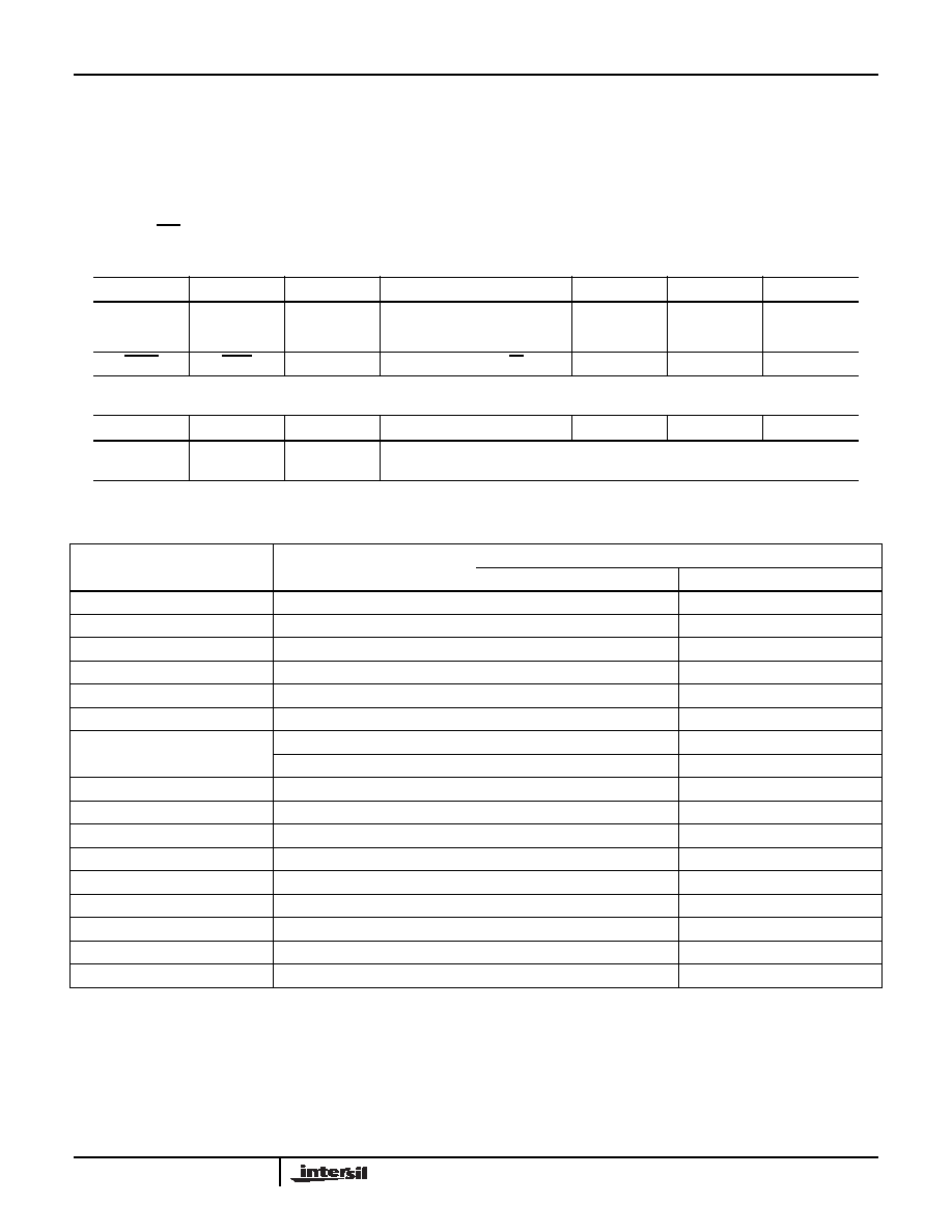
CLOCK CONTROL REGISTER (Write/Read) - Address 31H
D7
D6
D5
D4
D3
D2
D1
D0
START
LINE
XTAL
50Hz
CLK OUT
SEL
STOP
XTAL
10
60Hz
210
INTERRUPT CONTROL REGISTER (Write/Read) - Address 32H
D7
D6
D5
D4
D3
D2
D1
D0
WATCHDOG
POWER
DOWN
POWER
SENSE
ALARM
PERIODIC SELECT
NOTE: All bits are reset by power-on reset.
TABLE 3. PERIODIC INTERRUPT OUTPUT
D0 - D3 VALUE
PERIODIC INTERRUPT
OUTPUT FREQUENCY
FREQUENCY TIME BASE
XTAL
LINE
0
Disable
1
2048Hz
X
2
1024Hz
X
3
512Hz
X
4
256Hz
X
5
128Hz
X
6
64Hz
X
50Hz or 60Hz
X
7
32Hz
X
8
16Hz
X
98Hz
X
10
4Hz
X
11
2Hz
X
12
1Hz
X
13
Minute
X
14
Hour
X
15
Day
X
CDP68HC68T1
发布紧急采购,3分钟左右您将得到回复。
相关PDF资料
CPLL66-1600-2200
IC VCO PLL/SYNTH 2.2GHZ SMD
CPLL66-2175-2175
IC VCO PLL/SYNTH 2175MHZ SMD
CPLL66-2400-2500
IC VCO PLL/SYNTH 2500MHZ SMD
CPLL66-2450-2450
IC VCO PLL/SYNTH 2450MHZ SMD
CPLL66-3160-3380
IC VCO PLL/SYNTH 3380MHZ SMD
CPLL66-3475-3475
IC VCO PLL/SYNTH 3475MHZ SMD
CPLL66-4160-4380
IC VCO PLL/SYNTH 4380MHZ SMD
CPLL66-4240-4240
IC VCO PLL/SYNTH 4240MHZ SMD
相关代理商/技术参数
CDP68HC68T1M2
功能描述:实时时钟 PERIPH SPIAL-TIME- CLK 16W IND RoHS:否 制造商:Microchip Technology 功能:Clock, Calendar. Alarm RTC 总线接口:I2C 日期格式:DW:DM:M:Y 时间格式:HH:MM:SS RTC 存储容量:64 B 电源电压-最大:5.5 V 电源电压-最小:1.8 V 最大工作温度:+ 85 C 最小工作温度: 安装风格:Through Hole 封装 / 箱体:PDIP-8 封装:Tube
CDP68HC68T1M296
功能描述:实时时钟 PERIPH SPIAL-TIME- CLK 16W INDEL RoHS:否 制造商:Microchip Technology 功能:Clock, Calendar. Alarm RTC 总线接口:I2C 日期格式:DW:DM:M:Y 时间格式:HH:MM:SS RTC 存储容量:64 B 电源电压-最大:5.5 V 电源电压-最小:1.8 V 最大工作温度:+ 85 C 最小工作温度: 安装风格:Through Hole 封装 / 箱体:PDIP-8 封装:Tube
CDP68HC68T1M296S2357
制造商:Rochester Electronics LLC 功能描述:- Bulk
CDP68HC68T1M2Z
功能描述:实时时钟 PERI SPIAL-TIME-CLK RoHS:否 制造商:Microchip Technology 功能:Clock, Calendar. Alarm RTC 总线接口:I2C 日期格式:DW:DM:M:Y 时间格式:HH:MM:SS RTC 存储容量:64 B 电源电压-最大:5.5 V 电源电压-最小:1.8 V 最大工作温度:+ 85 C 最小工作温度: 安装风格:Through Hole 封装 / 箱体:PDIP-8 封装:Tube
CDP68HC68T1M2Z96
功能描述:实时时钟 PERI SPIAL-TIME-CLK RoHS:否 制造商:Microchip Technology 功能:Clock, Calendar. Alarm RTC 总线接口:I2C 日期格式:DW:DM:M:Y 时间格式:HH:MM:SS RTC 存储容量:64 B 电源电压-最大:5.5 V 电源电压-最小:1.8 V 最大工作温度:+ 85 C 最小工作温度: 安装风格:Through Hole 封装 / 箱体:PDIP-8 封装:Tube
CDP68HC68T1M96
功能描述:实时时钟 PERIPH SPIAL-TIME- CLK 20W INDEL RoHS:否 制造商:Microchip Technology 功能:Clock, Calendar. Alarm RTC 总线接口:I2C 日期格式:DW:DM:M:Y 时间格式:HH:MM:SS RTC 存储容量:64 B 电源电压-最大:5.5 V 电源电压-最小:1.8 V 最大工作温度:+ 85 C 最小工作温度: 安装风格:Through Hole 封装 / 箱体:PDIP-8 封装:Tube
CDP68HC68T1M96S2357
制造商:Rochester Electronics LLC 功能描述:- Bulk
CDP68HC68T1MZ
功能描述:实时时钟 W/ANEAL PERIPH SPIAL -TIME-CLK 20W IND RoHS:否 制造商:Microchip Technology 功能:Clock, Calendar. Alarm RTC 总线接口:I2C 日期格式:DW:DM:M:Y 时间格式:HH:MM:SS RTC 存储容量:64 B 电源电压-最大:5.5 V 电源电压-最小:1.8 V 最大工作温度:+ 85 C 最小工作温度: 安装风格:Through Hole 封装 / 箱体:PDIP-8 封装:Tube